前向渲染、延迟渲染和Forward+
项目最近计划要在移动平台上添加大量的动态光,计划使用Cluster Forward Plus,由于项目使用URP,别说CFP,延迟渲染现在还没被支持(据说之后Unity有支持的计划),所以需要我们自己实现。本文是对网络论文的整理,有部分是自己的理解,但大部分还是作者的论述。
简介
前端渲染就是通过栅格化场景的多边形对象来工作,迭代场景的灯光列表以确定几何对象如何被照亮。这意味着每个灯光并且每个场景物体都要被处理。当然,我们能通过不渲染被遮罩的或者在摄像机视锥之外的几何对象来优化。如果光的范围是已知的,我们也可以在渲染场景几何之前通过光的体积上执行视锥剔除。如此通过剔除的技术其实优化有限而且难以实践。更常见的做法是简单地限制可以影响场景对象的灯光数量。例如一些图形引擎会对最近的两三个灯光执行逐像素光照,对次近的进行逐顶点光照。传统OpenGL和DirectX固定函数渲染管线的动态光在场景被激活的的数量任何时候都被限制为8个。甚至在现代图形硬件中,如果没有明显的帧率问题,前端渲染会被限制到100个动态场景光源。
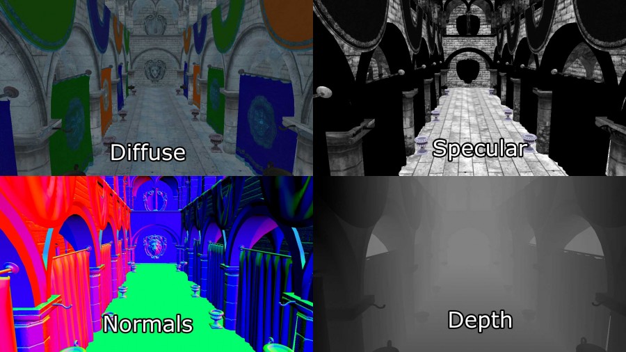
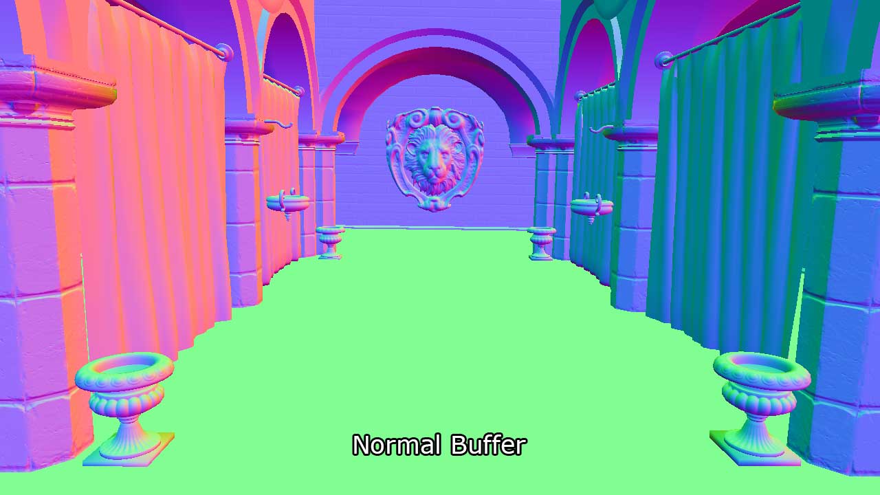
延迟渲染,换句话说,是通过栅格化场景对象(没有光照)为一系列的图像缓存,用于保存执行后面的光照计算的几何信息。保存为2D图像缓存的有:
- 屏幕空间深度
- 表面Normal
- diffuse颜色
- specular颜色和次幂
这些二维图像缓冲区的组合称为几何缓冲区(G-Buffer)。Specular的Power项保存在Specular的Alpha通道,见下图的右上角。
其他信息如果被光照计算并之后渲染,同样可以保存在图像缓存中。他们的G-buffer纹理HD(1080p)32位时至少占用8.29MB。
G-buffer创建后,几何信息能用来在光照通道里计算光照信息,每个像素被光的几何表现接触,就会通过期望的光照等式来着色。
延迟渲染技术相对前向渲染的明显好处就是,当在HD分辨率(1080p)只渲染不透明物体的时候,它能处理2500动态场景光照并且还没出现掉帧问题。
那为什么延迟渲染能比前向渲染更能处理大量光照呢?下图就能很好解释
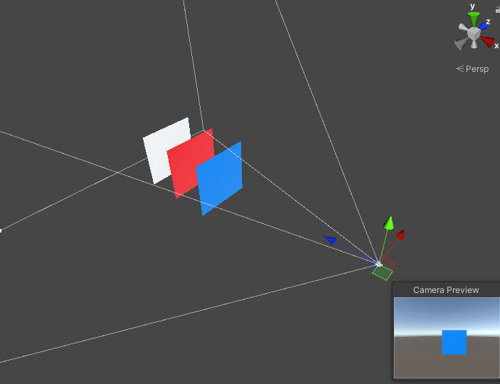
图中摄像机的视锥体内渲染了三个平面(蓝红白),右边是摄像机实际渲染的帧。可以看到,实际上物体只渲染到蓝色平面。根据DirectX可编程图形管线的顺序:
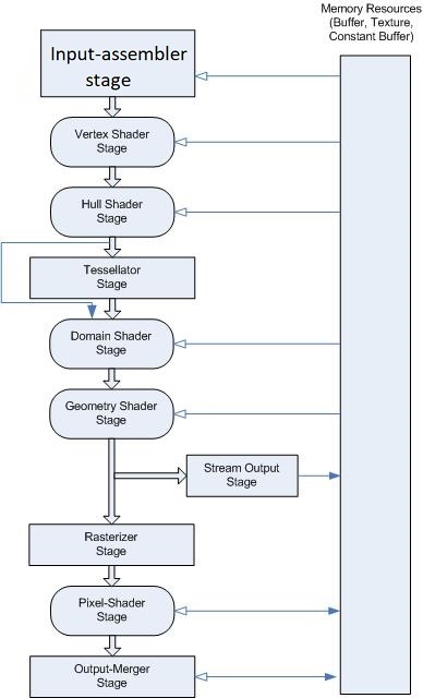
1、Pixel Shader进行光照计算
2、Ouput-Merger输出合并阶段进行深度测试
如此一来,前面的两个平面(白色和红色)会做了多余的光照计算,从而浪费了GPU的时钟周期。这是一盏灯的情况,灯光的数量如果多了,这是一个巨大浪费。
不过按照很多引擎的做法,不透明的物体是从摄像机近到远对物体排序,并进行渲染的。假如说深度测试在Pixel Shader之前(Early-Z),那么是否就能解决这种浪费呢?虽然这样做确实能节省大量的光照运算,但是场景上的物体,一般都是三维模型,模型之间有各种穿插,也有可能同一个模型在摄像机同一个视图空间位置多次渲染的情况,不可能只有上面三个面的情况的,物体的排序有时候根本解决不了如此问题。
延迟渲染相对前向渲染有两个缺点:
1、延迟渲染只能渲染不透明物体。这是由于多个透明物体有可能会覆盖同一个像素,而G-buffer在一个像素仅仅只能存一个值。在这个光照pass中,深度值,表面normal,diffuse和specular颜色,都会被最近被照亮的屏幕像素采样。因为每一个G-buffer仅仅能被采样到一个值,透明物体是不能被这光照pass支持的。要避免这个问题,透明物体必须用标准的前向的渲染技术,要么限制一下透明几何物体的数量,要么限制一下动态光的数量。而不透明物体一般能处理2000盏灯而不丢帧。
2、延迟渲染只能使用单一光照模型。这是由于在渲染几何体的光照的时候,它只能绑定单一pixel shader。如果你用单一光照shader,这不是什么麻烦事,如果不同的pixel shader实现了不一样的光照模型,延迟渲染管线就是个大问题了。
Forward+(又称tiled forward shading)是结合前向渲染和基于tiled的光剔除,减少光的数量,这是着色阶段必须被关注的。Forward+主要由两个阶段组成:
1、光照剔除
2、前向渲染
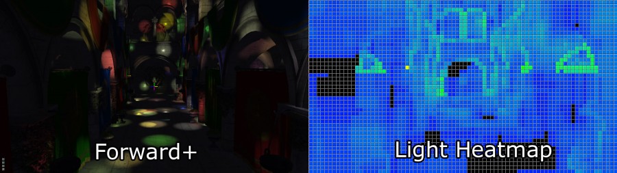
(上图为Forward+光照。默认光照(左边),光的热力图(右边)。热力图的颜色表明在一个tile中被多少个光影响。黑色的tiles不包含任何光,蓝色tiles包含1-10盏光。绿色tiles包含20-30盏光。)
Forward+渲染技术的第一个pass在屏幕空间使用统一的tiles格子,将光划分为每一个tile的列表。
第二个pass使用一个标准前向pass,在场景中进行着色,但不是循环每一个场景的动态光照,最近的像素的屏幕空间位置是被用于查找在前一个pass计算过的格子的光照列表。光照 剔除相较标准的前向渲染,提供一个极大的性能提升,因为它大大降低了那些必须被迭代来正确光照到对应像素。不透明和透明的几何体能被处理为一个类似的方式,没有重大的性能损耗和处理多个材质和光照模型,并且光照模型是自然地被Forward+支持。
因为Forwad+技术里包含标准前向渲染管线,Forward+能被整合为现存的使用前向构建的图形引擎中。Forward+不能使用 G-buffers和不受延迟渲染的限制。不透明物体和透明物体都能被Forward+渲染。使用现代图形硬件中,一个由5000-6000动态光组成的场景能在HD分辨率(1080p)中实时渲染。
在本文的剩余部分中,我会描述三点具体技术实现:
1、前向渲染
2、延迟渲染
3、Forward+(Tiles Forward Renderer)
同时我会显示基于不同情景的性能图表,以确定哪种条件下一种技术是优于另外的技术。
定义
下面将概况性地定义各个渲染的流程大纲:
前向渲染:
1、不透明pass
2、透明pass
不透明pass是以摄像机为目标,从近到远渲染,以降低overdraw。透明pass则是从远到近渲染,用于Alpha混合。
延迟渲染:
1、几何pass
2、光照pass
3、不透明pass
几何pass类似于前向的不透明pass,都是渲染不透明物体,只是它不进行光照计算,但它会几何信息写进G-buffer。而光照pass中,场景中代表光照几何物体和材质信息也会写进G-buffer。
Forward+:
1、光照剔除pass
2、不透明pass
3、透明pass
光照pass是对动态光在屏幕空间tiles中进行排序,光照索引列表则是对覆盖在屏幕tiles光照索引值。这个pass中会创建两组光照索引表:
1、不透明索引表
2、透明索引表
他们分别是用来渲染不透明和透明的光照。
而不透明pass和透明pass跟标准前向渲染是一样的,除了它只渲染剔除完毕的光。
本论文只支持:点光源、聚光灯、方向光,暂不支持区域光。点光源几何表现为球体,聚光灯为圆锥,方向光为全屏四边形。
前向渲染
前向渲染是大部分引擎的默认渲染管线(ue4默认是延迟)。这里简述一下通用的前向渲染的过程,不同引擎可能实现细节不一样。
前向渲染简单来说就是把场景所有光都遍历一遍进行渲染计算,所以它能使用的动态光是十分有限的,像UnityURP只支持8个额外光照,因为渲染压力实在是大。而一般引擎会离线光照来实现多光源的效果,譬如lightmapping和light probes,然而他们无法做动态光因为灯光信息在运行的时候已经被丢弃找不到了。
下面会描述前向渲染的实现细节,让它能跟延迟渲染和Forward+进行性能等数据对比。而且很多技术细节它都能跟延迟渲染和Forward+一样,比如vertex shader,或者是最终光照计算方法。
Vertex Shader:
顶点结构:
CommonInclude.hlsl
1
2
3
4
5
6
7
8
struct AppData
{
    float3 position : POSITION;
    float3 tangent  : TANGENT;
    float3 binormal : BINORMAL;
    float3 normal   : NORMAL;
    float2 texCoord : TEXCOORD0;
};
position是物体空间坐标,texCoord是纹理坐标,normal为法线,tangent,binormal则是用在normal map,要么是美术在建模时创建,要么导入的时候用工具创建。
然后还有对顶点变换的MVP矩阵和用于计算物体在view space的MV矩阵,这里用cbuffer来储存:
CommonInclude.hlsl
1
2
3
4
5
cbuffer PerObject : register( b0 )
{
    float4x4 ModelViewProjection;
    float4x4 ModelView;
}
然后是vertex shader的输出:
CommonInclude.hlsl
1
2
3
4
5
6
7
8
9
struct VertexShaderOutput
{
    float3 positionVS   : TEXCOORD0;    // View space position.
    float2 texCoord     : TEXCOORD1;    // Texture coordinate
    float3 tangentVS    : TANGENT;      // View space tangent.
    float3 binormalVS   : BINORMAL;     // View space binormal.
    float3 normalVS     : NORMAL;       // View space normal.
    float4 position     : SV_POSITION;  // Clip space position.
};
VS后缀的意思是view space,在view space空间的物体,ps使用view space而不是世界空间,是由于延迟渲染和Forward+实现方便。
对于前向渲染,SV_POSITION是在clip space的位置,对于延迟渲染和Forward+则是在屏幕空间的位置。
ForwardRendering.hlsl
1
2
3
4
5
6
7
8
9
10
11
12
13
14
15
VertexShaderOutput VS_main( AppData IN )
{
    VertexShaderOutput OUT;

    OUT.position = mul( ModelViewProjection, float4( IN.position, 1.0f ) );

    OUT.positionVS = mul( ModelView, float4( IN.position, 1.0f ) ).xyz;
    OUT.tangentVS = mul( ( float3x3 )ModelView, IN.tangent );
    OUT.binormalVS = mul( ( float3x3 )ModelView, IN.binormal );
    OUT.normalVS = mul( ( float3x3 )ModelView, IN.normal );

    OUT.texCoord = IN.texCoord;

    return OUT;
}
这里说一个关于矩阵的事。在DirectX10之后(之前都是右乘),DirectX在C++层面上,矩阵是用向量右乘的(row_major),而HLSL中矩阵则是左乘的(column_major),而OpenGL则都是左乘矩阵,左乘矩阵的标准,向量都是列向量,右乘矩阵则是行向量。个人更喜欢column_major,因为这样矩阵可读性比较高点,矩阵每一行代表一个分量(xyz)的变换结果。可参照Docs。
Pixel shader:
像素着色器的光照模型则是标准的 Blinn-Phong光照模型,这里不再赘述。
材质:
CommonInclude.hlsl
1
2
3
4
5
6
7
8
9
10
11
12
13
14
15
16
17
18
19
20
21
22
23
24
25
26
27
28
29
30
31
32
33
34
35
36
struct Material
{
    float4  GlobalAmbient;
    //-------------------------- ( 16 bytes )
    float4  AmbientColor;
    //-------------------------- ( 16 bytes )
    float4  EmissiveColor;
    //-------------------------- ( 16 bytes )
    float4  DiffuseColor;
    //-------------------------- ( 16 bytes )
    float4  SpecularColor;
    //-------------------------- ( 16 bytes )
    // Reflective value.
    float4  Reflectance;
    //-------------------------- ( 16 bytes )
    float   Opacity;
    float   SpecularPower;
    // For transparent materials, IOR > 0.
    float   IndexOfRefraction;
    bool    HasAmbientTexture;
    //-------------------------- ( 16 bytes )
    bool    HasEmissiveTexture;
    bool    HasDiffuseTexture;
    bool    HasSpecularTexture;
    bool    HasSpecularPowerTexture;
    //-------------------------- ( 16 bytes )
    bool    HasNormalTexture;
    bool    HasBumpTexture;
    bool    HasOpacityTexture;
    float   BumpIntensity;
    //-------------------------- ( 16 bytes )
    float   SpecularScale;
    float   AlphaThreshold;
    float2  Padding;
    //--------------------------- ( 16 bytes )
};  //--------------------------- ( 16 * 10 = 160 bytes )
GlobalAmbient是全局环境光,一般来说它应该定义为全局变量。
Ambient, Emissive, Diffuse, Specular就是 Blinn-Phong的四个项的光照颜色。
Reflectance是反射项颜色,这里没有对其具体实现。
Opacity为不透明度。
SpecularPower为Phong模型的幂次项。
IndexOfRefraction是折射索引,也是没有实现。
HasTexture定义是否使用纹理。
BumpIntensity在HasBumpTexture为True的时候,使用Bump Mapping而不是Normal Map时的效果强度。
SpecularScale是用来放大Specular纹理幂次的值。
AlphaThreshold是用来在pixel shader时discard低于这个alpha值的。使用它能不使用AlphaBlend的情况下渲染没有半透明的透明物体。
Padding是一个8字节占位符,虽然HLSL本身会自动暗中处理这事情让结构体16字节的倍数,不过这里这么写只是为了看起来直观。
CommonInclude.hlsl
1
2
3
4
cbuffer Material : register( b2 )
{
    Material Mat;
};
这些cbuffer会被文中所有的pixel shader使用。
纹理:
- Ambient
- Emissive
- Diffuse
- Specular
- SpecularPower
- Normals
- Bump
- Opacity
8张纹理,不是所有物体每张都在用。
CommonInclude.hlsl
1
2
3
4
5
6
7
8
Texture2D AmbientTexture        : register( t0 );
Texture2D EmissiveTexture       : register( t1 );
Texture2D DiffuseTexture        : register( t2 );
Texture2D SpecularTexture       : register( t3 );
Texture2D SpecularPowerTexture  : register( t4 );
Texture2D NormalTexture         : register( t5 );
Texture2D BumpTexture           : register( t6 );
Texture2D OpacityTexture        : register( t7 );
灯光:
点光源、聚光灯、方向光用的都是同一个结构,使用Type变量区分。
CommonInclude.hlsl
1
2
3
4
5
6
7
8
9
10
11
12
13
14
15
16
17
18
19
20
21
22
23
24
25
26
27
28
29
30
31
32
33
34
35
36
37
38
39
40
41
42
43
44
45
46
47
48
49
50
51
52
53
54
55
56
57
58
59
60
struct Light
{
    /**
    * Position for point and spot lights (World space).
    */
    float4   PositionWS;
    //--------------------------------------------------------------( 16 bytes )
    /**
    * Direction for spot and directional lights (World space).
    */
    float4   DirectionWS;
    //--------------------------------------------------------------( 16 bytes )
    /**
    * Position for point and spot lights (View space).
    */
    float4   PositionVS;
    //--------------------------------------------------------------( 16 bytes )
    /**
    * Direction for spot and directional lights (View space).
    */
    float4   DirectionVS;
    //--------------------------------------------------------------( 16 bytes )
    /**
    * Color of the light. Diffuse and specular colors are not seperated.
    */
    float4   Color;
    //--------------------------------------------------------------( 16 bytes )
    /**
    * The half angle of the spotlight cone.
    */
    float    SpotlightAngle;
    /**
    * The range of the light.
    */
    float    Range;

    /**
     * The intensity of the light.
     */
    float    Intensity;

    /**
    * Disable or enable the light.
    */
    bool    Enabled;
    //--------------------------------------------------------------( 16 bytes )

    /**
     * Is the light selected in the editor?
     */
    bool    Selected;

    /**
    * The type of the light.
    */
    uint    Type;
    float2  Padding;
    //--------------------------------------------------------------( 16 bytes )
    //--------------------------------------------------------------( 16 * 7 = 112 bytes )
};
位置和方向都分别保存了WS(世界空间)和VS(视图空间)。这是为了使用方便,10000盏灯光会额外占用1.12MB的内存,当然这也是可以优化掉的。
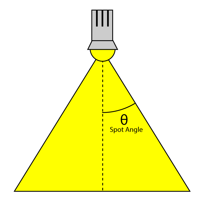
SpotlightAngle 是聚光灯垂直线与灯光边缘的夹角:
Range变量定义光照的影响距离,单位是米。点光源表示为半径,聚光灯表示为圆锥体的长,方向光则无用。
Intensity是光照强度,默认是1。
Enabled则是灯光的开关。
Type是灯光类型,定义如下:
CommonInclude.hlsl
1
2
3
#define POINT_LIGHT 0
#define SPOT_LIGHT 1
#define DIRECTIONAL_LIGHT 2
光照数组我们使用StructuredBuffer来储存。因为cbuffer被限制为64KB,这样光照数量会被限制为570lights,这样constant内存就爆了。而StructuredBuffer是用texture内存的,一般是被GPU纹理数量限制(桌面GPU肯定都是GB级的),而且texture内存也很快。
CommonInclude.hlsl
1
StructuredBuffer<Light> Lights : register( t8 );
下面继续Pixel Shader:
1
2
3
4
5
6
[earlydepthstencil]
float4 PS_main( VertexShaderOutput IN ) : SV_TARGET
{
    // Everything is in view space.
    float4 eyePos = { 0, 0, 0, 1 };
    Material mat = Mat;
[earlydepthstencil] 属性标识为GPU会使用early depth和stencil剔除,会在pixel shader之前进行深度/模板测试。很多GPU本身就有这种early测试,不过还是保留这个属性以防万一。
因为所有光照计算实在是视图空间中的,所以就不需要传递摄像机的坐标位置了,光照计算会比较方便。
ForwardRendering.hlsl
1
2
3
4
5
6
7
8
9
10
11
12
13
float4 diffuse = mat.DiffuseColor;
if ( mat.HasDiffuseTexture )
{
    float4 diffuseTex = DiffuseTexture.Sample( LinearRepeatSampler, IN.texCoord );
    if ( any( diffuse.rgb ) )
    {
        diffuse *= diffuseTex;
    }
    else
    {
        diffuse = diffuseTex;
    }
}
此处处理diffuse,其的意思是如果diffuse是(0, 0, 0),直接赋值diffuse纹理颜色,否则相乘。
下面Opacity、Ambient、Emissive、Specular等部分都是Blinn-Phong模型的实现,代码也有注释,这里就不在赘述。
法线:
如果既不用normal map,也不用bump map,将直接使用模型的normal。
ForwardRendering.hlsl
1
2
3
4
5
6
7
8
9
10
11
12
13
14
15
16
17
18
19
20
21
22
23
24
25
// Normal mapping
if ( mat.HasNormalTexture )
{
    // For scenes with normal mapping, I don't have to invert the binormal.
    float3x3 TBN = float3x3( normalize( IN.tangentVS ),
                             normalize( IN.binormalVS ),
                             normalize( IN.normalVS ) );

    N = DoNormalMapping( TBN, NormalTexture, LinearRepeatSampler, IN.texCoord );
}
// Bump mapping
else if ( mat.HasBumpTexture )
{
    // For most scenes using bump mapping, I have to invert the binormal.
    float3x3 TBN = float3x3( normalize( IN.tangentVS ),
                             normalize( -IN.binormalVS ),
                             normalize( IN.normalVS ) );

    N = DoBumpMapping( TBN, BumpTexture, LinearRepeatSampler, IN.texCoord, mat.BumpIntensity );
}
// Just use the normal from the model.
else
{
    N = normalize( float4( IN.normalVS, 0 ) );
}
Normal Mapping
CommonInclude.hlsl
1
2
3
4
5
6
7
8
9
10
11
12
13
14
float3 ExpandNormal( float3 n )
{
    return n * 2.0f - 1.0f;
}

float4 DoNormalMapping( float3x3 TBN, Texture2D tex, sampler s, float2 uv )
{
    float3 normal = tex.Sample( s, uv ).xyz;
    normal = ExpandNormal( normal );

    // Transform normal from tangent space to view space.
    normal = mul( normal, TBN );
    return normalize( float4( normal, 0 ) );
}
Bump Mapping
不同于Normal Mapping,使用的是高度图。法线通过计算纹理中高度的斜率。算法类似Normal,都是基于切线空间,详细细节可参考相关Bump Mapping技术文章。
CommonInclude.hlsl
1
2
3
4
5
6
7
8
9
10
11
12
13
14
15
16
17
18
19
20
21
float4 DoBumpMapping( float3x3 TBN, Texture2D tex, sampler s, float2 uv, float bumpScale )
{
    // Sample the heightmap at the current texture coordinate.
    float height = tex.Sample( s, uv ).r * bumpScale;
    // Sample the heightmap in the U texture coordinate direction.
    float heightU = tex.Sample( s, uv, int2( 1, 0 ) ).r * bumpScale;
    // Sample the heightmap in the V texture coordinate direction.
    float heightV = tex.Sample( s, uv, int2( 0, 1 ) ).r * bumpScale;

    float3 p = { 0, 0, height };
    float3 pU = { 1, 0, heightU };
    float3 pV = { 0, 1, heightV };

    // normal = tangent x bitangent
    float3 normal = cross( normalize(pU - p), normalize(pV - p) );

    // Transform normal from tangent space to view space.
    normal = mul( normal, TBN );

    return float4( normal, 0 );
}
光照:
整个光照算法都在DoLighting函数中实现,有如下参数:
lights:灯光数组,StructuredBuffer
mat:材质属性
eyePos:摄像机位置,因为是在视图空间,始终为(0,0,0)。
P:着色位置,视图空间
N:着色Normal,视图空间
ForwardRendering.hlsl
1
2
3
4
5
6
7
8
9
10
11
12
13
14
15
16
17
18
19
20
21
22
23
24
25
26
27
28
29
30
31
32
33
34
35
36
37
38
39
40
41
42
43
44
45
46
47
48
// This lighting result is returned by the
// lighting functions for each light type.
struct LightingResult
{
    float4 Diffuse;
    float4 Specular;
};

LightingResult DoLighting( StructuredBuffer<Light> lights, Material mat, float4 eyePos, float4 P, float4 N )
{
    float4 V = normalize( eyePos - P );

    LightingResult totalResult = (LightingResult)0;

    for ( int i = 0; i < NUM_LIGHTS; ++i )
    {
        LightingResult result = (LightingResult)0;

        // Skip lights that are not enabled.
        if ( !lights[i].Enabled ) continue;
        // Skip point and spot lights that are out of range of the point being shaded.
        if ( lights[i].Type != DIRECTIONAL_LIGHT &&
             length( lights[i].PositionVS - P ) > lights[i].Range ) continue;

        switch ( lights[i].Type )
        {
        case DIRECTIONAL_LIGHT:
        {
            result = DoDirectionalLight( lights[i], mat, V, P, N );
        }
        break;
        case POINT_LIGHT:
        {
            result = DoPointLight( lights[i], mat, V, P, N );
        }
        break;
        case SPOT_LIGHT:
        {
            result = DoSpotLight( lights[i], mat, V, P, N );
        }
        break;
        }
        totalResult.Diffuse += result.Diffuse;
        totalResult.Specular += result.Specular;
    }

    return totalResult;
}
Diffuse:
CommonInclude.hlsl
1
2
3
4
5
float4 DoDiffuse( Light light, float4 L, float4 N )
{
    float NdotL = max( dot( N, L ), 0 );
    return light.Color * NdotL;
}
Specular:
CommonInclude.hlsl
1
2
3
4
5
6
7
float4 DoSpecular( Light light, Material material, float4 V, float4 L, float4 N )
{
    float4 R = normalize( reflect( -L, N ) );
    float RdotV = max( dot( R, V ), 0 );

    return light.Color * pow( RdotV, material.SpecularPower );
}
衰减:
光照的衰减传统光照模型是:三个衰减因子的和乘以光照距离的倒数。
- 常数衰减
- 线性衰减
- 二次衰减
但是这些方法里光照的值是无法衰减到0的,对于Forward+和延迟渲染必须有个有限范围的方法来计算衰减。其中有个方法是在光照范围内的,对光照强度从1开始进行线性混合,不在范围的则为0。但这方法不大真实,因为真是的衰减应该是一个二次函数的倒数。不过smoothstep可以替代线性混合来解决这问题。
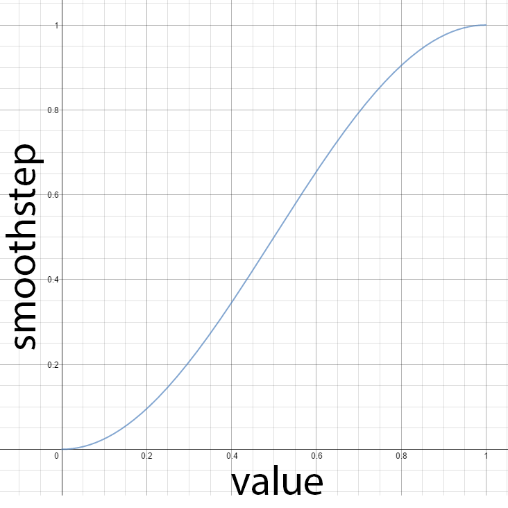
CommonInclude.hlsl
1
2
3
4
5
// Compute the attenuation based on the range of the light.
float DoAttenuation( Light light, float d )
{
    return 1.0f - smoothstep( light.Range * 0.75f, light.Range, d );
}
上面的做法是当与灯光距离低于3/4的时候,smoothstep返回为0。
点光源:
ForwardRendering.hlsl
1
2
3
4
5
6
7
8
9
10
11
12
13
14
15
16
17
LightingResult DoPointLight( Light light, Material mat, float4 V, float4 P, float4 N )
{
    LightingResult result;

    float4 L = light.PositionVS - P;
    float distance = length( L );
    L = L / distance;

    float attenuation = DoAttenuation( light, distance );

    result.Diffuse = DoDiffuse( light, L, N ) *
                      attenuation * light.Intensity;
    result.Specular = DoSpecular( light, mat, V, L, N ) *
                       attenuation * light.Intensity;

    return result;
}
聚光灯:
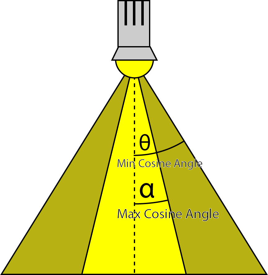
此聚光灯的做法是:内角无衰减,内角到外角开始进行smoothstep插值。外角指的是聚光灯的角度,内角则是外角一半的位置,当然smoothstep的参数是点到灯光距离与灯光方向的点积,而且刚好cos也是与角度负相关。
CommonInclude.hlsl
1
2
3
4
5
6
7
8
9
10
11
12
13
14
float DoSpotCone( Light light, float4 L )
{
    // If the cosine angle of the light's direction
    // vector and the vector from the light source to the point being
    // shaded is less than minCos, then the spotlight contribution will be 0.
    float minCos = cos( radians( light.SpotlightAngle ) );
    // If the cosine angle of the light's direction vector
    // and the vector from the light source to the point being shaded
    // is greater than maxCos, then the spotlight contribution will be 1.
    float maxCos = lerp( minCos, 1, 0.5f );
    float cosAngle = dot( light.DirectionVS, -L );
    // Blend between the minimum and maximum cosine angles.
    return smoothstep( minCos, maxCos, cosAngle );
}
ForwardRendering.hlsl
1
2
3
4
5
6
7
8
9
10
11
12
13
14
15
16
17
18
LightingResult DoSpotLight( Light light, Material mat, float4 V, float4 P, float4 N )
{
    LightingResult result;

    float4 L = light.PositionVS - P;
    float distance = length( L );
    L = L / distance;

    float attenuation = DoAttenuation( light, distance );
    float spotIntensity = DoSpotCone( light, L );

    result.Diffuse = DoDiffuse( light, L, N ) *
                       attenuation * spotIntensity * light.Intensity;
    result.Specular = DoSpecular( light, mat, V, L, N ) *
                       attenuation * spotIntensity * light.Intensity;

    return result;
}
方向光:
方向光最简单了,没有衰减距离不需要衰减函数。
ForwardRendering.hlsl
1
2
3
4
5
6
7
8
9
10
11
LightingResult DoDirectionalLight( Light light, Material mat, float4 V, float4 P, float4 N )
{
    LightingResult result;

    float4 L = normalize( -light.DirectionVS );

    result.Diffuse = DoDiffuse( light, L, N ) * light.Intensity;
    result.Specular = DoSpecular( light, mat, V, L, N ) * light.Intensity;

    return result;
}
最后我们对它进行各项最终相加处理:
ForwardRendering.hlsl
1
2
3
4
5
6
7
8
9
10
11
12
13
14
15
16
17
18
19
20
21
22
23
24
25
26
27
28
29
    float4 P = float4( IN.positionVS, 1 );

    LightingResult lit = DoLighting( Lights, mat, eyePos, P, N );

    diffuse *= float4( lit.Diffuse.rgb, 1.0f ); // Discard the alpha value from the lighting calculations.

    float4 specular = 0;
    if ( mat.SpecularPower > 1.0f ) // If specular power is too low, don't use it.
    {
        specular = mat.SpecularColor;
        if ( mat.HasSpecularTexture )
        {
            float4 specularTex = SpecularTexture.Sample( LinearRepeatSampler, IN.texCoord );
            if ( any( specular.rgb ) )
            {
                specular *= specularTex;
            }
            else
            {
                specular = specularTex;
            }
        }
        specular *= lit.Specular;
    }

    return float4( ( ambient + emissive + diffuse + specular ).rgb,
                     alpha * mat.Opacity );

}
延迟渲染
本文的G-buffer不是最高效的,很多设计可以简化buffer的数量和大小。本文暂不探讨过多的优化方案。
以下是我们要创建的G-buffer:
- Depth/Stencil
- Light Accumulation
- Diffuse
- Specular
- Normals
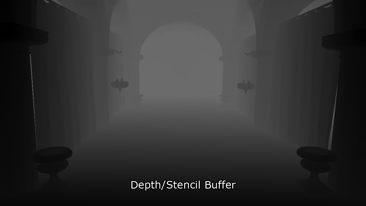
Depth/Stencil Buffer
该纹理是32bit,包含24bit的深度值,是一个无符号归一化浮点数(UNORM),8bit是模板值,为无符号整型(UINT)。depth buffer可以创建为R24G8_TYPELESS,depth/stencil view则被创建为D24_UNORM_S8_UINT。我们不使用stencil,shader resource view会被创建为R24_UNORM_X8_TYPELESS。
depth/stencil缓存会依附到输出合并阶段,不会在pixel shader直接计算G-buffer。vertex shader的结果会直接写进depth/stencil buffer。
Light Accumulation Buffer
这个buffer一半保存光照pass的最终结果,我们这里主要保存emissive和ambient项。如果G-buffer分辨率跟屏幕一样,可以直接使用back buffer从而减少buffer的创建。光照累积buffer是保存为32bit,R8G8B8A8_UNORM,纹理资源和shader resource view都一样。
收集方向光可以跳过光照pass的方向光处理,因为方向光是全屏效果,通过这方法可以优化GPU填充率,但还需要再加一张方向光的buffer,本文还要顾及前向渲染和Forward+也不多讨论此方案。
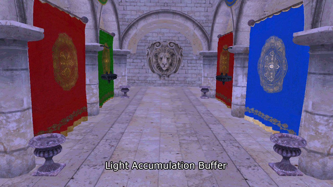
上图保存的是emissive和ambient项,为了看起来清晰点上图被大大照亮。
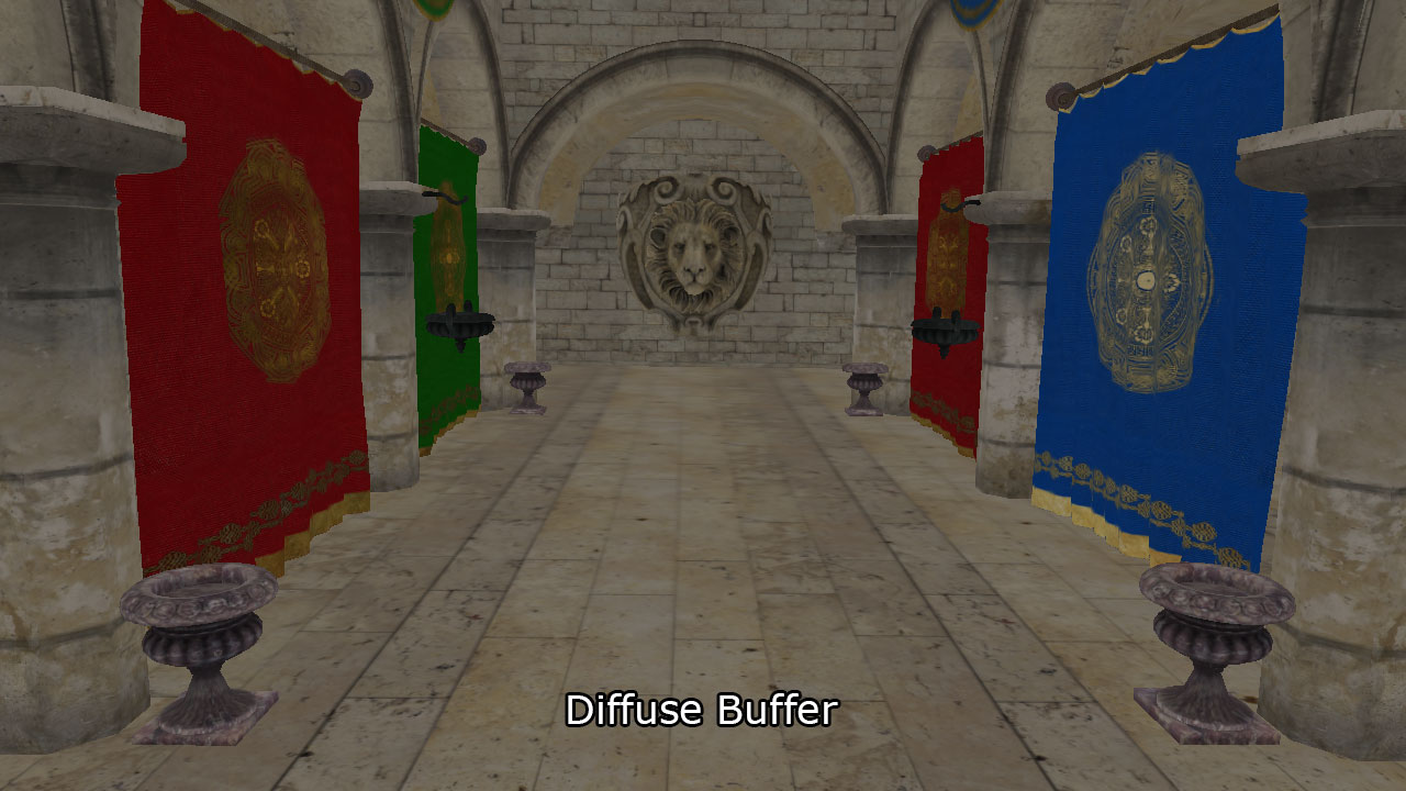
Diffuse Buffer
32bit的buffer,R8G8B8A8_UNORM纹理和shader resource view的格式。因为渲染的都是不透明物体,Alpha分享其实可以优化掉。
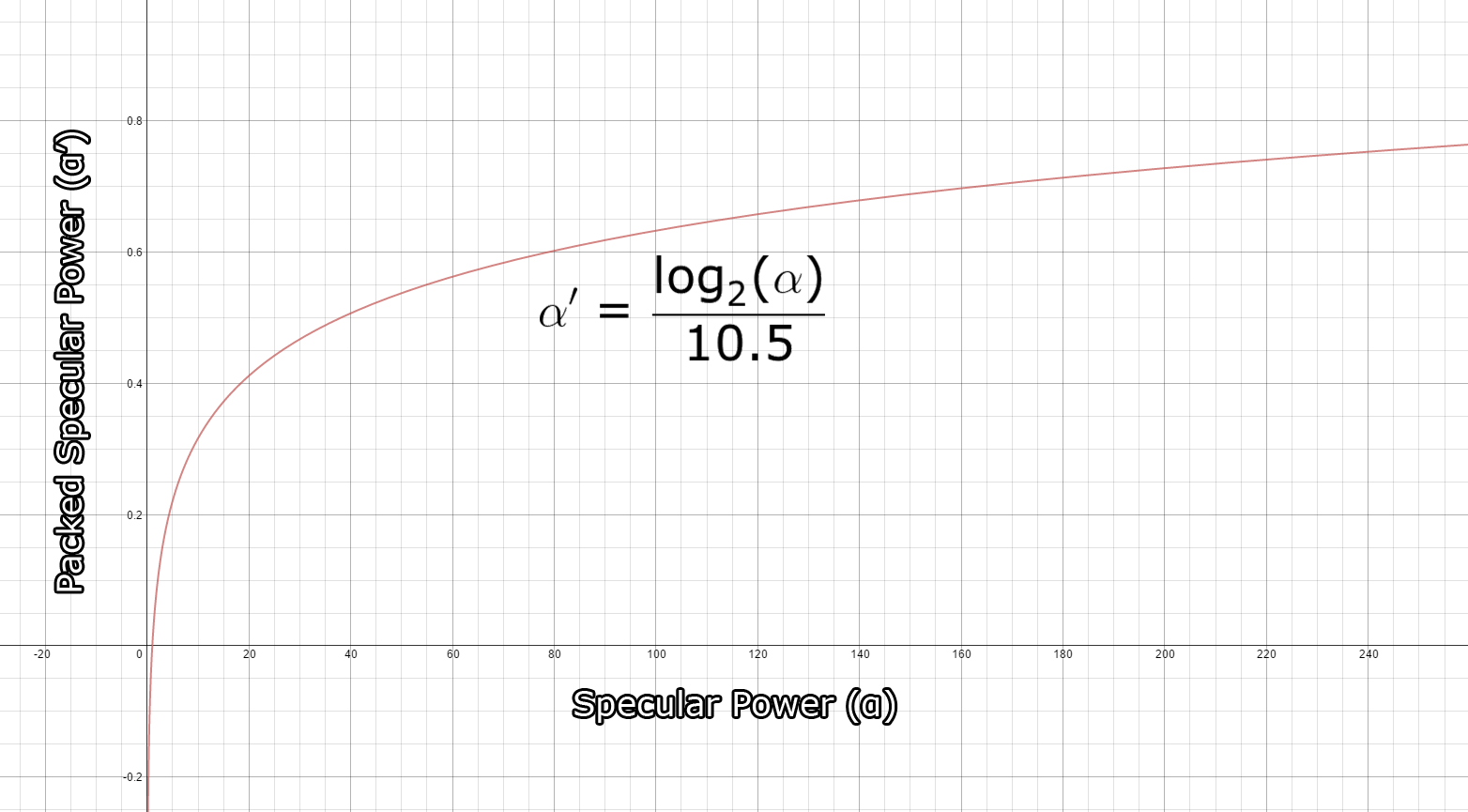
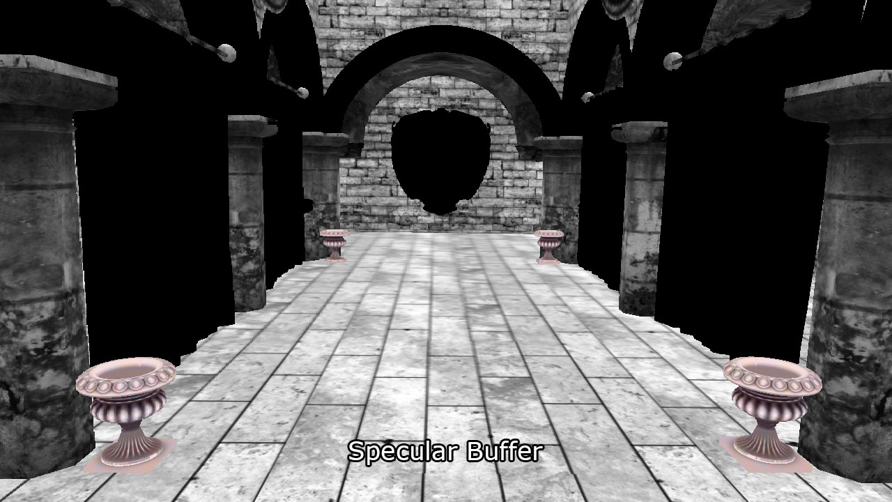
Specular Buffer
类似 light accumulation和the diffuse buffers, 使用32bit,R8G8B8A8_UNORM的纹理格式。RGB通道保存specular颜色,alpha保存power值。power值范围是(1 … 256],但是需要打包成(0 … 1]。打包算法由Michiel van der Leeuw的 “Deferred Rendering in Killzone 2”提供,公式如下: \(\alpha’=\frac{\log_2(\alpha)}{10.5}\) 这个函数的打包范围为[1…1448.15] ,对 (1…256)的精度非常不错。下图是打包的输出结果的函数图像,横坐标是输入,纵坐标是输出:
specular buffer输出结果:
Normal Buffer
视图空间的normal被保存为128-bit浮点数,R32G32B32A32_FLOAT纹理格式。一般来说大可以保存更低的格式,如R16G16_FLOAT,效果不会差很多,这里只为了精度保存为较大的纹理。
G-buffer的布局总结
| R | G | B | A | |
|---|---|---|---|---|
| DEPTH/STENCIL | D24_UNORM | S8_UINT | ||
| LIGHT ACCUMULATION | R8_UNORM | G8_UNORM | B8_UNORM | A8_UNORM |
| DIFFUSE | R8_UNORM | G8_UNORM | B8_UNORM | A8_UNORM |
| SPECULAR | R8_UNORM | G8_UNORM | B8_UNORM | A8_UNORM |
| NORMAL | R32_FLOAT | G32_FLOAT | B32_FLOAT | A32_FLOAT |
Pixel Shader
G-Buffer pass的ps的计算流程基本上跟前向渲染差不多,不一样的地方在于G-buffer pass不会进行光照运算。
这里使用PixelShaderOutput结构体作为输出
DeferredRendering.hlsl
1
2
3
4
5
6
7
struct PixelShaderOutput
{
    float4 LightAccumulation    : SV_Target0;
    float4 Diffuse              : SV_Target1;
    float4 Specular             : SV_Target2;
    float4 NormalVS             : SV_Target3;
};
因为depth/stencil buffer绑定与输出合并阶段,这里不需要输出深度图。
DeferredRendering.hlsl
1
2
3
4
5
6
7
8
9
10
11
12
13
14
15
16
[earlydepthstencil]
PixelShaderOutput PS_Geometry( VertexShaderOutput IN )
{
    PixelShaderOutput OUT;

    // Get emissive, ambient, diffuse, specular and normal values
    // In the same way as the forward rendering pixel shader.
    // The source code is not shown here for the sake of brevity.

    OUT.LightAccumulation = ( ambient + emissive );
    OUT.Diffuse = diffuse;
    OUT.Specular = float4( specular.rgb, log2( specularPower ) / 10.5f );
    OUT.NormalVS = N;

    return OUT;
}
所有G-buffer结果都输出到RenderTarget里,这里只简略地写一下代码,详细过程参考项目源码。
G-buffer pass结束后,就轮到Lighting pass了。下面会使用两种方法:Guerrilla公司方法和自行实现的方法。
Lighting Pass (Guerrilla公司的实现)
本文延迟渲染光照pass是由索尼娱乐的Michiel van der Leeuw于2007年8月于旧金山Palo Alto的演讲 “Deferred Rendering in Killzone 2” ,其描述Lighting Pass应该分四个阶段:
- 清理stencil buffer
- 对灯光远边界进行标记
- 统计在灯光体积内被照亮的像素
- 给照亮灯光着色
标记边界的目的,是为了标记那些像素需要被照明。下面只简述一下后面三个阶段。
标记像素
假设灯光体积是一个实体,对于点光源它就是一个球的实体。这个球体的背面,我们标记这些像素并写入模板缓存。在这之前需要把模板缓存清理为0,然后:
- 绑定vertex shader (不需要pixel shader)
- 在合并阶段绑定depth/stencil buffer(因为没有pixel shader,不需要绑定color buffer)
- 栅格化状态:
- 将灯光体积的cull mode设置为FRONT
- Depth/Stencil状态:
- 开启depth testing
- 关闭depth writes
- 设置depth function为了GREATER_EQUAL
- 开启stencil operations
- 设置stencil reference 为1
- 设置stencil function 为ALWAYS
- 设置stencil operation为 REPLACE
这是在深度pass中操作stencil的,如图可见:虚线是灯光体积的正面,已经被剔除,只会渲染其背面。绿色体积部分则在stencil缓存中标记为stencil reference的值,由图可见有两个正方体都被标记进去了,显然最近的那个正方体不应该被照明:
![]()
统计像素
现在被标记的像素明显还并不正确,所以还需要处理灯光体积的正面部分,再进行一次标记,又称统计像素。配置如下:
- 绑定vertex shader (不需要pixel shader)
- 在合并阶段绑定depth/stencil buffer(因为没有pixel shader,不需要绑定color buffer)
- 栅格化状态:
- 将灯光体积的cull mode设置为BACK
- Depth/Stencil状态:
- 开启depth testing
- 关闭depth writes
- 设置depth function为了LESS_EQUAL
- 开启stencil operations
- 设置stencil reference 为1
- 设置stencil function 为KEEP
- 设置stencil operation为EQUAL
通过遮罩的像素查询,就能实现如此像素统计,效果如图:
![]()
红色部分就是这个阶段的执行结果,也是最终要被该灯光照明的相关像素。另外Michiel的这次演讲也涉及到灯光阴影的创建,但不在本文的讨论范围内。
灯光着色
最后的阶段就是对物体的灯光着色了,最后结果只会对灯光体积内的像素进行着色,配置跟统计像素阶段基本一样,出了多了个混合状态:
绑定vertex shader (不需要pixel shader)
在合并阶段绑定depth/stencil buffer(因为没有pixel shader,不需要绑定color buffer)
栅格化状态:
- 将灯光体积的cull mode设置为BACK
Depth/Stencil状态:
- 开启depth testing
- 关闭depth writes
- 设置depth function为了LESS_EQUAL
- 开启stencil operations
- 设置stencil reference 为1
- 设置stencil function 为KEEP
- 设置stencil operation为EQUAL
Blend State:
- 开启Blend
- 设置source factor为ONE
- 设置destination factor为ONE
- 设置blend operation为ADD
Lighting Pass(另外一种实现)
Michiel演讲的这种Lighting Pass有个问题,就是查询像素操作(标记像素和统计像素),会让CPU等待GPU的完成而卡顿,这可以通过查询上一帧或者上两帧的结果而不是查询当前帧来避免。不过这样会到导致每个光源要有多个查询对象,因为如果查询对象是持续多帧的,这就不能复用了。
而此方法的另外一个问题是,如果摄像机在灯光体积内,统计像素阶段就会有问题,因为它已经被剔除了,如图:

绿色体积部分为标记像素阶段,这里没什么问题,但是这里就没有统计像素的红色部分,因为灯光体积的前向面已被视锥体剔除了。我这里尝试关闭深度裁剪,然而无济于事。
为解决问题,我尝试反转Michiel的方法:
1、用1来清理模板缓存
2、对灯光的近边界进行反标记
3、对在灯光远边界进行着色
像素反标记
使用此方法可以把近边界前面的物体进行反标记,吧近边界前面的物体给剔除:
- 绑定vertex shader (不需要pixel shader)
- 在合并阶段绑定depth/stencil buffer(因为没有pixel shader,不需要绑定color buffer)
- 栅格化状态:
- 将灯光体积的cull mode设置为BACK
- Depth/Stencil状态:
- 开启depth testing
- 关闭depth writes
- 设置depth function为了GREATER
- 开启stencil operations
- 设置stencil reference 为1
- 设置stencil function 为ALWAYS
- 设置stencil operation为DECR_SAT
![]()
DECR_SAT是对stencil减一,并且保持在[0,1]范围。绿色范围就是被反标记的部分。
像素着色
- 绑定vertex shader (不需要pixel shader)
- 在合并阶段绑定depth/stencil buffer(因为没有pixel shader,不需要绑定color buffer)
- 栅格化状态:
- 将灯光体积的cull mode设置为FRONT
- 关闭深度clipping
- Depth/Stencil状态:
- 开启depth testing
- 关闭depth writes
- 设置depth function为了GREATER_EQUAL
- 开启stencil operations
- 设置stencil reference 为1
- 设置stencil function 为KEEP
- 设置stencil operation为EQUAL
- Blend State:
- 开启Blend
- 设置source factor为ONE
- 设置destination factor为ONE
- 设置blend operation为ADD
上面关闭深度clipping是为了防止灯光体积超过远裁面的时候不会被裁掉。下面是效果:
![]()
通过之前的像素反标记,现在这个阶段会把近边界和远边界里面的物体,也即是灯光体积内的物体进行渲染,就是红色体积部分。
Pixel Shader
这个Pixel Shader仅在这个阶段绑定,获取G-buffer数据并且跟前向渲染一样的模型。因为光照计算都是在视图空间中的,我们需要把屏幕空间到视图空间的转换过程。下面实现了ClipToView 和ScreenToView 函数,用来分别实现裁剪空间到视图空间,和屏幕空间到视图空间。然后我们也需要两个参数:
CommonInclude.hlsl
1
2
3
4
5
6
// Parameters required to convert screen space coordinates to view space.
cbuffer ScreenToViewParams : register( b3 )
{
    float4x4 InverseProjection;
    float2 ScreenDimensions;
}
InverseProjection是投影矩阵的逆矩阵,ScreenDimensions为屏幕宽高。
CommonInclude.hlsl
1
2
3
4
5
6
7
8
9
10
11
12
13
14
15
16
17
18
19
20
21
22
// Convert clip space coordinates to view space
float4 ClipToView( float4 clip )
{
    // View space position.
    float4 view = mul( InverseProjection, clip );
    // Perspective projection.
    view = view / view.w;

    return view;
}

// Convert screen space coordinates to view space.
float4 ScreenToView( float4 screen )
{
    // Convert to normalized texture coordinates
    float2 texCoord = screen.xy / ScreenDimensions;

    // Convert to clip space
    float4 clip = float4( float2( texCoord.x, 1.0f - texCoord.y ) * 2.0f - 1.0f, screen.z, screen.w );

    return ClipToView( clip );
}
ScreenToView中,首先把屏幕坐标归一化,也即是([0…SCREEN_WIDTH], [0…SCREEN_HEIGHT]) 转换为 ([0…1], [0..1])。然后因为DirectX的屏幕原点(0,0)是在左上角,y轴是从上到下递增的。所以我们首先把y轴反转,然后缩放为[0..2]范围,然后通过-1再变换到[-1…1]范围。

在ClipToView中,通过于乘以投影矩阵的逆,并且除以w来移除透视投影。
DeferredRendering.hlsl
1
2
3
4
5
6
7
8
9
10
[earlydepthstencil]
float4 PS_DeferredLighting( VertexShaderOutput IN ) : SV_Target
{
    // Everything is in view space.
    float4 eyePos = { 0, 0, 0, 1 };

    int2 texCoord = IN.position.xy;
    float depth = DepthTextureVS.Load( int3( texCoord, 0 ) ).r;

    float4 P = ScreenToView( float4( texCoord, depth, 1.0f ) );
IN输入的位置信息是屏幕空间的,因为它来自G-Buffer的四方形。我们使用Texture2D.Load而不是Texture2D.Sample是因为Load输入int3而不是float3,z轴是mipmap level,是位于纹理空间texel space,没有归一化,这里是0,否则更低的mipmap level会返回黑色。然后Texture2D.Load性能上显著比Texture2D.Sample强是因为它不需要线性过滤。
下面是光照流程,跟前向类似。
DeferredRendering.hlsl
1
2
3
4
5
6
7
8
9
// View vector
float4 V = normalize( eyePos - P );

float4 diffuse = DiffuseTextureVS.Load( int3( texCoord, 0 ) );
float4 specular = SpecularTextureVS.Load( int3( texCoord, 0 ) );
float4 N = NormalTextureVS.Load( int3( texCoord, 0 ) );

// Unpack the specular power from the alpha component of the specular color.
float specularPower = exp2( specular.a * 10.5f );
1
2
3
4
5
cbuffer LightIndexBuffer : register( b4 )
{
    // The index of the light in the Lights array.
    uint LightIndex;
}
1
2
3
4
5
6
7
8
9
10
11
12
13
14
15
16
17
18
19
20
21
22
23
24
    Light light = Lights[LightIndex];

    Material mat = (Material)0;
    mat.DiffuseColor = diffuse;
    mat.SpecularColor = specular;
    mat.SpecularPower = specularPower;

    LightingResult lit = (LightingResult)0;

    switch ( light.Type )
    {
    case DIRECTIONAL_LIGHT:
        lit = DoDirectionalLight( light, mat, V, P, N );
        break;
    case POINT_LIGHT:
        lit = DoPointLight( light, mat, V, P, N );
        break;
    case SPOT_LIGHT:
        lit = DoSpotLight( light, mat, V, P, N );
        break;
    }

    return ( diffuse * lit.Diffuse ) + ( specular * lit.Specular );
}
你会发现这里不需要检查灯光是否开启。因为在lighting pass的标记光阶段已经把没启用的光被剔除掉了。然后最后返回所有光照累加。
透明通道
开始也说了,透明通道是无法被延迟渲染处理的,只能使用前向管线渲染,在用延迟渲染不透明物体之后,再使用前向管线渲染透明物体即可。
Forward+
Forward+是前向渲染的改进,它首先检查到屏幕空间那些光会被重叠。然后在着色阶段只会关心”潜在“的叠加片元。为什么说”潜在“是因为查找重叠的光不是十分准确,后面会说到。Foward+主要由三个部分组成:
- Light culling
- Opaque pass
- Transparent pass
不透明通道会有一个专门的在lighting pass创建的灯光列表,不是所有灯光都会被渲染,只有在划分到当前屏幕对应的片元的才会被计算。而透明通道也是近似但有所不同,下面会详述。
网格截锥
要实现光照的剔除,需要生成每个网格的剔除截锥。因为剔除截锥是基于视图空间的,一半来说只要在网格发生变化的时候才会重建(比如屏幕宽高发生变化)。屏幕将被划分为大量的正方形瓦片,我把这个称之为光照网格light grid。网格的数量应该遵从DirectX的compute shader,线程组里的线程数需要是64的倍数(能充分利用GPU的双曲调度器)且不能超过1024。有三种候选方案:
- 8×8 (每组64 线程)
- 16×16 (每组256线程)
- 32×32 (每组1024线程)
假设我们选用16x16方案,且每个网格包含16x16像素。

上图就是16x16线程组的部分网格。粗线是划分线程组,细线是划分为线程。光照剔除用的瓦片是跟线程一样的划分方案,如下图:

截锥有六个面,这里先计算上下左右四个面:
- 在屏幕空间计算四个边角点
- 把四个点变换到视图空间下的远平面
- 构建截锥平面并且保存到 RWStructuredBuffer
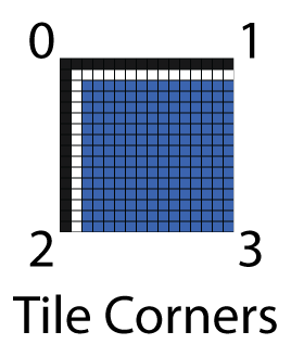
在逆时针顺序下:
- Left Plane: Eye, Bottom-Left (2), Top-Left (0)
- Right Plane: Eye, Top-Right (1), Bottom-Right (3)
- Top Plane: Eye, Top-Left (0), Top-Right (1)
- Bottom Plane: Eye, Bottom-Right (3), Bottom-Left (2)

已知不共线的三点ABC,可得平面法线n: \(n=(B−A)×(C−A)\) 归一化后的n与平面上的一点P可得平面到原点的距离: \(d=n⋅P\) 也可以用参数方程表示: \(ax+by+cz−d=0\) n=(a,b,c) X=(x,y,z),X是平面上任意一点。
在HLSL可以这样定义平面:
CommonInclude.hlsl
1
2
3
4
5
struct Plane
{
    float3 N;   // Plane normal.
    float  d;   // Distance to origin.
};
通过不共线的三点计算平面:
CommonInclude.hlsl
1
2
3
4
5
6
7
8
9
10
11
12
13
14
15
16
17
// Compute a plane from 3 noncollinear points that form a triangle.
// This equation assumes a right-handed (counter-clockwise winding order)
// coordinate system to determine the direction of the plane normal.
Plane ComputePlane( float3 p0, float3 p1, float3 p2 )
{
    Plane plane;

    float3 v0 = p1 - p0;
    float3 v2 = p2 - p0;

    plane.N = normalize( cross( v0, v2 ) );

    // Compute the distance to the origin using p0.
    plane.d = dot( plane.N, p0 );

    return plane;
}
截锥则表示为:
CommonInclude.hlsl
1
2
3
4
5
6
7
8
9
10
11
12
// Four planes of a view frustum (in view space).
// The planes are:
//  * Left,
//  * Right,
//  * Top,
//  * Bottom.
// The back and/or front planes can be computed from depth values in the
// light culling compute shader.
struct Frustum
{
    Plane planes[4];   // left, right, top, bottom frustum planes.
};
计算网格的截锥,需要涉及到每个网格的瓦片compute shader kernel。假设屏幕分辨率是1280x720,并且每个网格分为16x16瓦片(一个瓦片是一个像素),这样就要计算80x45(3600)个截锥(一个网格一个截锥)。如果线程组包含16x16个线程,那么我们就需要5x2.8125个线程组,当然我们无法只取一部分的线程组,所以应该取整为5x3个线程组,每组16x16线程,如图粗线划分线程组,细线划分线程,蓝色是运行的线程,红色是多余出来不需要执行的线程,每个小方块内包含16x16个瓦片(像素),也即是每个线程需要处理16x16个瓦片:

shader声明如下:
ForwardPlusRendering.hlsl
1
2
3
4
5
6
7
8
9
10
11
12
#ifndef BLOCK_SIZE
#pragma message( "BLOCK_SIZE undefined. Default to 16.")
#define BLOCK_SIZE 16 // should be defined by the application.
#endif

struct ComputeShaderInput
{
    uint3 groupID           : SV_GroupID;           // 3D index of the thread group in the dispatch.
    uint3 groupThreadID     : SV_GroupThreadID;     // 3D index of local thread ID in a thread group.
    uint3 dispatchThreadID  : SV_DispatchThreadID;  // 3D index of global thread ID in the dispatch.
    uint  groupIndex        : SV_GroupIndex;        // Flattened local index of the thread within a thread group.
};
声明用于线程的cbuffer:
ForwardPlusRendering.hlsl
1
2
3
4
5
6
7
8
9
10
11
12
13
// Global variables
cbuffer DispatchParams : register( b4 )
{
    // Number of groups dispatched. (This parameter is not available as an HLSL system value!)
    uint3   numThreadGroups;
    // uint padding // implicit padding to 16 bytes.

    // Total number of threads dispatched. (Also not available as an HLSL system value!)
    // Note: This value may be less than the actual number of threads executed
    // if the screen size is not evenly divisible by the block size.
    uint3   numThreads;
    // uint padding // implicit padding to 16 bytes.
}
声明输出截锥:
ForwardPlusRendering.hlsl
1
2
// View space frustums for the grid cells.
RWStructuredBuffer<Frustum> out_Frustums : register( u0 );
屏幕空间中的边角瓦片
在compute shader中,我们通过使用全局线程ID来获得,为什么z是-1是因为这里使用右手坐标系,如果你使用左右坐标系则是1:
ForwardPlusRendering.hlsl
1
2
3
4
5
6
7
8
9
10
11
12
13
14
15
16
17
18
19
20
21
// A kernel to compute frustums for the grid
// This kernel is executed once per grid cell. Each thread
// computes a frustum for a grid cell.
[numthreads( BLOCK_SIZE, BLOCK_SIZE, 1 )]
void CS_ComputeFrustums( ComputeShaderInput IN )
{
    // View space eye position is always at the origin.
    const float3 eyePos = float3( 0, 0, 0 );

    // Compute the 4 corner points on the far clipping plane to use as the
    // frustum vertices.
    float4 screenSpace[4];
    // Top left point
    screenSpace[0] = float4( IN.dispatchThreadID.xy * BLOCK_SIZE, -1.0f, 1.0f );
    // Top right point
    screenSpace[1] = float4( float2( IN.dispatchThreadID.x + 1, IN.dispatchThreadID.y ) * BLOCK_SIZE, -1.0f, 1.0f );
    // Bottom left point
    screenSpace[2] = float4( float2( IN.dispatchThreadID.x, IN.dispatchThreadID.y + 1 ) * BLOCK_SIZE, -1.0f, 1.0f );
    // Bottom right point
    screenSpace[3] = float4( float2( IN.dispatchThreadID.x + 1, IN.dispatchThreadID.y + 1 ) * BLOCK_SIZE, -1.0f, 1.0f );
视图空间中的瓦片
ForwardPlusRendering.hlsl
1
2
3
4
5
6
float3 viewSpace[4];
// Now convert the screen space points to view space
for ( int i = 0; i < 4; i++ )
{
    viewSpace[i] = ScreenToView( screenSpace[i] ).xyz;
}
计算截锥平面
ForwardPlusRendering.hlsl
1
2
3
4
5
6
7
8
9
10
11
// Now build the frustum planes from the view space points
Frustum frustum;

// Left plane
frustum.planes[0] = ComputePlane( eyePos, viewSpace[2], viewSpace[0] );
// Right plane
frustum.planes[1] = ComputePlane( eyePos, viewSpace[1], viewSpace[3] );
// Top plane
frustum.planes[2] = ComputePlane( eyePos, viewSpace[0], viewSpace[1] );
// Bottom plane
frustum.planes[3] = ComputePlane( eyePos, viewSpace[3], viewSpace[2] );
输出网格截锥
ForwardPlusRendering.hlsl
1
2
3
4
5
6
7
    // Store the computed frustum in global memory (if our thread ID is in bounds of the grid).
    if ( IN.dispatchThreadID.x < numThreads.x && IN.dispatchThreadID.y < numThreads.y )
    {
        uint index = IN.dispatchThreadID.x + ( IN.dispatchThreadID.y * numThreads.x );
        out_Frustums[index] = frustum;
    }
}
光照剔除
计算网格截锥只需要在游戏启动或者游戏resize的时候才要执行,而光照剔除则需要每次在物体移动或者光照移动的时候帧执行。其过程是:
- 计算瓦片的最小和最大深度
- 剔除并把光放到索引列表
- 将灯光索引列表赋值到全局内存
计算瓦片的最大/最小深度值,又称Depth Prepass
下面计算瓦片最大/最小深度值,这是用来构建剔除截锥的前和后裁剪平面的。如图1-7是瓦片的截锥,蓝色不透明物体,黄色是灯光,灰色是最大最小的截锥深度范围:

瓦片1的最小深度是从不透明物体1开始,然后到最大。瓦片2最小深度和最大深度都是从不透明物体1部分,因为它整个视野都被1遮挡住了。瓦片3则是从不透明物体1开始,从不透明物体2结束。
而透明的阶段的最小深度则是从近平面开始,因为透明物体是需要渲染不透明前面的任何东西,而且不能遮挡。在Markus Billeter, Ola Olsson, 和Ulf Assarsson的论文 “Tiled Forward Shading”中的解决方案是创建两个灯光列表,不透明灯光列表和透明灯光列表,分别对不透明和透明的照明。

灯光列表的数据结构
这个灯光列表的数据结构来自Markus Billeter, Ola Olsson, 和Ulf Assarsson的论文 “Tiled Forward Shading”,其分为两个部分:1、灯光网格是一个二位数组,用来保存灯光索引列表的偏移和数量。这种技术类似顶点索引和顶点buffer的关系。

如上图是光照网格的数据结构。假设1280x720的的分辨率,每个网格为16x16,那么会有80x45(3600)个网格。假设平均每个网格平均有200盏光,则需要72000个索引,索引使用32bit无符号整型,每个4字节,那么需要2.88MB内存,两个光照列表(透明和不透明)则是5.76MB。
下面是光照剔除的伪代码:
1
2
3
4
5
6
7
8
9
10
11
12
13
14
15
16
17
18
19
20
function CullLights( L, C, G, I )
    Input: L是光照集合.
    Input: C是全局光照索引列表的最近索引的数量。
    Input: G是在全局光照索引列表的偏移和数量。
    Output: G是上面G的输出
    Output: 本网格的的光照索引列表

1.  let t = 最近网格索引
2.  let i = 本地光照索引列表
3.  let f = 网格的截锥

4.  for l in L                      //迭代光照集合
5.      if Cull( l, f )             //通过截锥进行剔除
6.          AppendLight( l, i )     //赋值到光照索引列表

7.  c = AtomicInc( C, i.count )    //对最近的全局光照索引列表进行自增,增值为本网格的灯光数量,c									   //为源索引值

8.  G(t) = ( c, i.count )         //在全局算索引列表保存偏移和数量

9.  I(c) = i                      //输出本网格索引列表
截锥剔除
截锥剔除有两个步骤:
- 球-截锥算法用来剔除点光源
- 圆锥-截锥算法用来剔除聚光灯
球-截锥剔除算法
CommonInclude.hlsl
1
2
3
4
5
6
7
8
9
10
11
struct Sphere
{
    float3 c;   // Center point.
    float  r;   // Radius.
};
// Check to see if a sphere is fully behind (inside the negative halfspace of) a plane.
// Source: Real-time collision detection, Christer Ericson (2005)
bool SphereInsidePlane( Sphere sphere, Plane plane )
{
    return dot( plane.N, sphere.c ) - plane.d < -sphere.r;
}
要计算球是否在截锥内,需要先求球是否在平面的负半空间(negative half-space)内。如果球完全是在负半空间内的话,那它就不在截锥内。 \(l=(c⋅n)−d\) l是带符号平面到球的距离,c是球中心,n是平面归一化法线,d是平面到原点距离。
CommonInclude.hlsl
1
2
3
4
5
6
// Check to see if a sphere is fully behind (inside the negative halfspace of) a plane.
// Source: Real-time collision detection, Christer Ericson (2005)
bool SphereInsidePlane( Sphere sphere, Plane plane )
{
    return dot( plane.N, sphere.c ) - plane.d < -sphere.r;
}
截锥-圆锥剔除剔除算法
技术来源于是Christer Ericson的书 “Real-Time Collision Detection” 。

CommonInclude.hlsl
1
2
3
4
5
6
7
struct Cone
{
    float3 T;   // Cone tip.
    float  h;   // Height of the cone.
    float3 d;   // Direction of the cone.
    float  r;   // bottom radius of the cone.
};
类似球剔除算法,需要检测圆锥是否在平面负半空间内,需要检测两个点是否在平面负半空间内:
- 圆锥的尖端T
- 在n方向中距离平面最远的点Q
首先求得中间向量m: \(m=(n×d)×d\) 得Q: \(Q=T+hd−rm\) 若n×d 是0,则 \(Q=T+hd\) 然后跟球一样,带入X求得l: \(l=(n⋅X)−d\) CommonInclude.hlsl
1
2
3
4
5
6
7
8
9
10
11
12
13
14
15
16
17
18
19
20
21
22
23
24
25
26
27
28
29
// Check to see if a point is fully behind (inside the negative halfspace of) a plane.
bool PointInsidePlane( float3 p, Plane plane )
{
    return dot( plane.N, p ) - plane.d < 0;
}
bool ConeInsideFrustum( Cone cone, Frustum frustum, float zNear, float zFar )
{
    bool result = true;

    Plane nearPlane = { float3( 0, 0, -1 ), -zNear };
    Plane farPlane = { float3( 0, 0, 1 ), zFar };

    // First check the near and far clipping planes.
    if ( ConeInsidePlane( cone, nearPlane ) || ConeInsidePlane( cone, farPlane ) )
    {
        result = false;
    }

    // Then check frustum planes
    for ( int i = 0; i < 4 && result; i++ )
    {
        if ( ConeInsidePlane( cone, frustum.planes[i] ) )
        {
            result = false;
        }
    }

    return result;
}
光照剔除的compute shader
这需要构建两个索引列表,分别是不透明和透明物体,我们用”o_“和”t_“区分。下面代码DepthTextureVS是用过深度Prepass渲染出来的纹理。
ForwardPlusRendering.hlsl
1
2
3
4
5
6
7
8
9
10
11
12
13
14
15
16
17
18
// The depth from the screen space texture.
Texture2D DepthTextureVS : register( t3 );
// Precomputed frustums for the grid.
StructuredBuffer<Frustum> in_Frustums : register( t9 );

groupshared uint uMinDepth;
groupshared uint uMaxDepth;
groupshared Frustum GroupFrustum;

// Opaque geometry light lists.
groupshared uint o_LightCount;
groupshared uint o_LightIndexStartOffset;
groupshared uint o_LightList[1024];

// Transparent geometry light lists.
groupshared uint t_LightCount;
groupshared uint t_LightIndexStartOffset;
groupshared uint t_LightList[1024];
然后是AppendLight的实现:
ForwardPlusRendering.hlsl
1
2
3
4
5
6
7
8
9
10
11
12
13
14
15
16
17
18
19
20
21
// Add the light to the visible light list for opaque geometry.
void o_AppendLight( uint lightIndex )
{
    uint index; // Index into the visible lights array.
    InterlockedAdd( o_LightCount, 1, index );
    if ( index < 1024 )
    {
        o_LightList[index] = lightIndex;
    }
}

// Add the light to the visible light list for transparent geometry.
void t_AppendLight( uint lightIndex )
{
    uint index; // Index into the visible lights array.
    InterlockedAdd( t_LightCount, 1, index );
    if ( index < 1024 )
    {
        t_LightList[index] = lightIndex;
    }
}
InterlockedAdd是用来保证用group-shared声明的o_LightCount的线程同步,只会被一个线程修改。
计算最小最大深度范围是来自Johan Andersson演讲”DirectX 11 Rendering in Battlefield 3”以及Ola Olsson and Ulf Assarsson的演讲”Tiled Shading”。
ForwardPlusRendering.hlsl
1
2
3
4
5
6
7
8
9
10
11
12
13
14
// Implementation of light culling compute shader is based on the presentation
// "DirectX 11 Rendering in Battlefield 3" (2011) by Johan Andersson, DICE.
// Retrieved from: http://www.slideshare.net/DICEStudio/directx-11-rendering-in-battlefield-3
// Retrieved: July 13, 2015
// And "Forward+: A Step Toward Film-Style Shading in Real Time", Takahiro Harada (2012)
// published in "GPU Pro 4", Chapter 5 (2013) Taylor & Francis Group, LLC.
[numthreads( BLOCK_SIZE, BLOCK_SIZE, 1 )]
void CS_main( ComputeShaderInput IN )
{
    // Calculate min & max depth in threadgroup / tile.
    int2 texCoord = IN.dispatchThreadID.xy;
    float fDepth = DepthTextureVS.Load( int3( texCoord, 0 ) ).r;

    uint uDepth = asuint( fDepth );
使用asuint把深度转换为整型,这是位赋值的转换方法(Interprets ),因为以后要转回float,不能做任何数学运算,但是可以用来做大小对比。
ForwardPlusRendering.hlsl
1
2
3
4
5
6
7
8
9
10
if ( IN.groupIndex == 0 ) // Avoid contention by other threads in the group.
{
    uMinDepth = 0xffffffff;
    uMaxDepth = 0;
    o_LightCount = 0;
    t_LightCount = 0;
    GroupFrustum = in_Frustums[IN.groupID.x + ( IN.groupID.y * numThreadGroups.x )];
}

GroupMemoryBarrierWithGroupSync();
GroupMemoryBarrierWithGroupSync是防止出现竞争条件的错误,让组内所有线程都等待直到所有线程都执行到这里。
ForwardPlusRendering.hlsl
1
2
3
4
InterlockedMin( uMinDepth, uDepth );
InterlockedMax( uMaxDepth, uDepth );

GroupMemoryBarrierWithGroupSync();
InterlockedMin和InterlockedMax是原子更新其值。
ForwardPlusRendering.hlsl
1
2
3
4
5
6
7
8
9
10
11
float fMinDepth = asfloat( uMinDepth );
float fMaxDepth = asfloat( uMaxDepth );

// Convert depth values to view space.
float minDepthVS = ClipToView( float4( 0, 0, fMinDepth, 1 ) ).z;
float maxDepthVS = ClipToView( float4( 0, 0, fMaxDepth, 1 ) ).z;
float nearClipVS = ClipToView( float4( 0, 0, 0, 1 ) ).z;

// Clipping plane for minimum depth value
// (used for testing lights within the bounds of opaque geometry).
Plane minPlane = { float3( 0, 0, -1 ), -minDepthVS };
然后是各种灯光的处理方法
1
2
3
4
5
6
7
8
9
10
11
12
13
14
15
16
17
18
19
20
21
22
23
24
25
26
27
28
29
30
31
32
33
34
35
36
37
38
39
40
41
42
43
44
45
46
47
48
49
switch ( light.Type )
{
case POINT_LIGHT:
{
    Sphere sphere = { light.PositionVS.xyz, light.Range };
    if ( SphereInsideFrustum( sphere, GroupFrustum, nearClipVS, maxDepthVS ) )
    {
        // Add light to light list for transparent geometry.
        t_AppendLight( i );

        if ( !SphereInsidePlane( sphere, minPlane ) )
        {
            // Add light to light list for opaque geometry.
            o_AppendLight( i );
        }
    }
}
break;
case SPOT_LIGHT:
{
    float coneRadius = tan( radians( light.SpotlightAngle ) ) * light.Range;
    Cone cone = { light.PositionVS.xyz, light.Range, light.DirectionVS.xyz, coneRadius };
    if ( ConeInsideFrustum( cone, GroupFrustum, nearClipVS, maxDepthVS ) )
    {
        // Add light to light list for transparent geometry.
        t_AppendLight( i );

        if ( !ConeInsidePlane( cone, minPlane ) )
        {
            // Add light to light list for opaque geometry.
            o_AppendLight( i );
        }
    }
}
break;
        case DIRECTIONAL_LIGHT:
        {
            // Directional lights always get added to our light list.
            // (Hopefully there are not too many directional lights!)
            t_AppendLight( i );
            o_AppendLight( i );
        }
        break;
        }
    }
}

// Wait till all threads in group have caught up.
GroupMemoryBarrierWithGroupSync();
最终着色
这个阶段基本跟前向渲染差不多,出了多了个通过瓦片索引获取灯光列表。
ForwardPlusRendering.hlsl
1
2
3
4
5
6
7
8
9
10
11
12
13
14
15
16
17
18
19
20
21
22
23
24
25
26
27
28
29
30
31
32
33
34
35
36
37
38
39
40
41
42
43
44
45
46
47
48
49
50
[earlydepthstencil]
float4 PS_main( VertexShaderOutput IN ) : SV_TARGET
{
    // Compute ambient, emissive, diffuse, specular, and normal
    // similar to standard forward rendering.
    // That code is omitted here for brevity.

    // Get the index of the current pixel in the light grid.
    uint2 tileIndex = uint2( floor(IN.position.xy / BLOCK_SIZE) );

    // Get the start position and offset of the light in the light index list.
    uint startOffset = LightGrid[tileIndex].x;
    uint lightCount = LightGrid[tileIndex].y;

    LightingResult lit = (LightingResult)0; // DoLighting( Lights, mat, eyePos, P, N );

    for ( uint i = 0; i < lightCount; i++ )
    {
        uint lightIndex = LightIndexList[startOffset + i];
        Light light = Lights[lightIndex];

        LightingResult result = (LightingResult)0;

        switch ( light.Type )
        {
        case DIRECTIONAL_LIGHT:
        {
            result = DoDirectionalLight( light, mat, V, P, N );
        }
        break;
        case POINT_LIGHT:
        {
            result = DoPointLight( light, mat, V, P, N );
        }
        break;
        case SPOT_LIGHT:
        {
            result = DoSpotLight( light, mat, V, P, N );
        }
        break;
        }
        lit.Diffuse += result.Diffuse;
        lit.Specular += result.Specular;
    }

    diffuse *= float4( lit.Diffuse.rgb, 1.0f ); // Discard the alpha value from the lighting calculations.
    specular *= lit.Specular;

    return float4( ( ambient + emissive + diffuse + specular ).rgb, alpha * mat.Opacity );
}
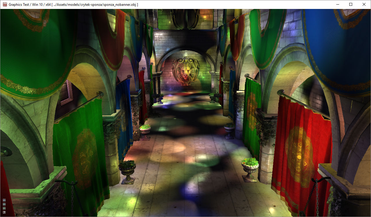
如图是使用Forward+一万个灯光。到此三种渲染管线的原理已介绍完毕。之后我们会给出这这种管线的性能对比。
项目工程下载
References
[1] T. Saito and T. Takahashi, ‘Comprehensible rendering of 3-D shapes’, ACM SIGGRAPH Computer Graphics, vol. 24, no. 4, pp. 197-206, 1990.
[2] T. Harada, J. McKee and J. Yang, ‘Forward+: Bringing Deferred Lighting to the Next Level’, Computer Graphics Forum, vol. 0, no. 0, pp. 1-4, 2012.
[3] T. Harada, J. McKee and J. Yang, ‘Forward+: A Step Toward Film-Style Shading in Real Time’, in GPU Pro 4, 1st ed., W. Engel, Ed. Boca Raton, Florida, USA: CRC Press, 2013, pp. 115-135.
[4] M. Billeter, O. Olsson and U. Assarsson, ‘Tiled Forward Shading’, in GPU Pro 4, 1st ed., W. Engel, Ed. Boca Raton, Florida, USA: CRC Press, 2013, pp. 99-114.
[5] O. Olsson and U. Assarsson, ‘Tiled Shading’, Journal of Graphics, GPU, and Game Tools, vol. 15, no. 4, pp. 235-251, 2011.
[6] Unity Technologies, ‘Unity - Manual: Light Probes’, Docs.unity3d.com, 2015. [Online]. Available: http://docs.unity3d.com/Manual/LightProbes.html. [Accessed: 04- Aug- 2015].
[7] Assimp.sourceforge.net, ‘Open Asset Import Library’, 2015. [Online]. Available: http://assimp.sourceforge.net/. [Accessed: 10- Aug- 2015].
[8] Msdn.microsoft.com, ‘Semantics (Windows)’, 2015. [Online]. Available: https://msdn.microsoft.com/en-us/library/windows/desktop/bb509647(v=vs.85).aspx. [Accessed: 10- Aug- 2015].
[9] Msdn.microsoft.com, ‘Variable Syntax (Windows)’, 2015. [Online]. Available: https://msdn.microsoft.com/en-us/library/windows/desktop/bb509706(v=vs.85).aspx. [Accessed: 10- Aug- 2015].
[10] Msdn.microsoft.com, ‘earlydepthstencil (Windows)’, 2015. [Online]. Available: https://msdn.microsoft.com/en-us/library/windows/desktop/ff471439(v=vs.85).aspx. [Accessed: 11- Aug- 2015].
[11] Crytek.com, ‘Crytek3 Downloads’, 2015. [Online]. Available: http://www.crytek.com/cryengine/cryengine3/downloads. [Accessed: 12- Aug- 2015].
[12] Graphics.cs.williams.edu, ‘Computer Graphics Data - Meshes’, 2015. [Online]. Available: http://graphics.cs.williams.edu/data/meshes.xml. [Accessed: 12- Aug- 2015].
[13] M. van der Leeuw, ‘Deferred Rendering in Killzone 2’, SCE Graphics Seminar, Palo Alto, California, 2007.
[14] Msdn.microsoft.com, ‘D3D11_DEPTH_STENCIL_DESC structure (Windows)’, 2015. [Online]. Available: https://msdn.microsoft.com/en-us/library/windows/desktop/ff476110(v=vs.85).aspx. [Accessed: 13- Aug- 2015].
[15] Electron9.phys.utk.edu, ‘Coherence’, 2015. [Online]. Available: http://electron9.phys.utk.edu/optics421/modules/m5/Coherence.htm. [Accessed: 14- Aug- 2015].
[16] Msdn.microsoft.com, ‘Load (DirectX HLSL Texture Object) (Windows)’, 2015. [Online]. Available: https://msdn.microsoft.com/en-us/library/windows/desktop/bb509694(v=vs.85).aspx. [Accessed: 14- Aug- 2015].
[17] Msdn.microsoft.com, ‘Compute Shader Overview (Windows)’, 2015. [Online]. Available: https://msdn.microsoft.com/en-us/library/windows/desktop/ff476331(v=vs.85).aspx. [Accessed: 04- Sep- 2015].
[18] C. Ericson, Real-time collision detection. Amsterdam: Elsevier, 2005.
[19] J. Andersson, ‘DirectX 11 Rendering in Battlefield 3’, 2011.
[20] Msdn.microsoft.com, ‘Volume Tiled Resources (Windows)’, 2015. [Online]. Available: https://msdn.microsoft.com/en-us/library/windows/desktop/dn903951(v=vs.85).aspx. [Accessed: 29- Sep- 2015].
[21] G. Thomas, ‘Advancements in Tiled-Based Compute Rendering’, San Francisco, California, USA, 2015.
[22] J. Arvo, ‘A Simple Method for Box-Sphere Intersection Testing’, in Graphics Gems, 1st ed., A. Glassner, Ed. Academic Press, 1990.
[23] O. Olsson, M. Billeter and U. Assarsson, ‘Clustered Deferred and Forward Shading’, High Performance Graphics, 2012.
[24] C. Crassin and S. Green, ‘Octree-Based Sparse Voxelization Using the GPU Hardware Rasterizer’, in OpenGL Insights, 1st ed., P. Cozzi and C. Riccio, Ed. CRC Press, 2012, p. Chapter 22.
[25] Mediacollege.com, ‘Three Point Lighting’, 2015. [Online]. Available: http://www.mediacollege.com/lighting/three-point/. [Accessed: 02- Oct- 2015].